Description :
The IR to RF transmitter circuit given here can convert the IR signals from your remote to RF signals to long distances. The circuit given here is a good one for extending the range of your IR remote.Also such systems does not need a line of sight since RF signals are used.
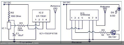
The transmitter is based on a St-TX 01 ASK transmitter IC (IC2).The IR signals falling on IC 1 (TSOP 1738) will be converted to RF signals by IC2 and transmitted through antenna.The transmitter has a power output of 16dBm at 5V supply.
The receiver is based on a ST-RX04 ASK receiver IC (IC3).The IC3 receives the transmitted code, decodes it to the original IR code and re transmits through IR LED (D1). The transistor Q1 is used to drive the D1 from the output of the IC3(pin2).
Circuit diagram with Parts list :
- Use a 6V power provide with a 1N 4007 series(forward biased) with its positive terminal as power for each Circuit.
- Use 20 cm long copper cable for each aerial.
- Ranges up to 200m are possible with related aerial.
- The capacitor C1 must be ranked 10V.
©2012, Copyright Raju's Tech World
Sunday, March 25, 2012
//
Labels:
Circuits Lab
//
1 comments
//
1 comments to "Circuit On IR to RF converter"


Unknown says:
i'm searching for ir to rf circuit.
have you tested this circuit? is this working?